
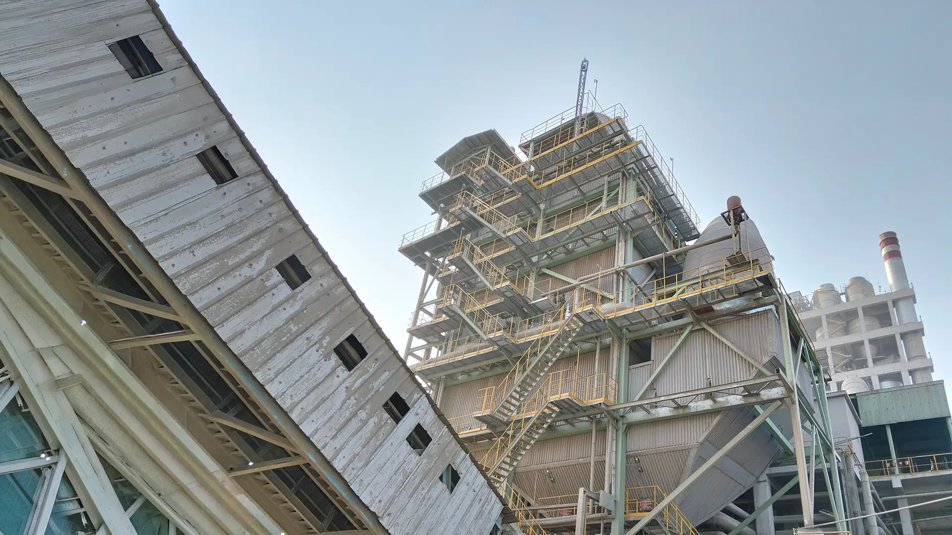
Waste Heat Boiler
Process Gas Cooler and Steam drum assembly of a Sulfur Recovery Unit for a fabricator in India.
Waste Heat Boiler
Overview
This project scope included Mechanical design, FEA of Flexible tubesheet and Piping Flexibility of the Riser Down comer piping.
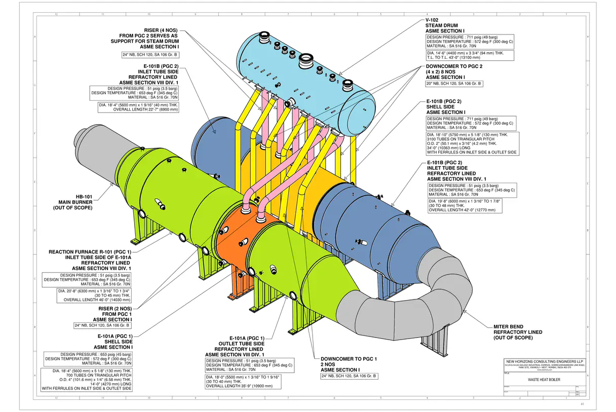
Mechanical design consisting of calculations to ASME Section I and ASME Section VIII Div 1, FEA of thin tubesheets which are refractory lined to protect the same from the very high operating temperatures and Piping flexibility analysis of Riser Downcomer piping between the Process gas coolers and the Steam drum which mounted on the coolers in piggy back fashion. The complete assembly is supported on multiple saddles.

Mechanical Design
The Shell side of both Process Gas coolers 1 and 2 and the steam drum were designed to ASME Section I. Mathcad sheets were developed inhouse for this purpose and then validated before submitting the same. The refractory lined channel side of both process gas coolers were designed to ASME Sec VIII Div 1 using PVElite software based on cold wall design consideration. Tubes were checked for design conditions of both shell side and channel side. The main burner and miter bend were excluded from our scope of work.
Finite Element Analysis
Channel side Inlet of Coolers is from the reaction furnace which is refractory lined to shield the vessel wall from high temperature process gas of about 1650 deg F. To protect the face of tubesheet and the inlet portion of the tubes, a combination of ceramic ferrules, cerapaper and castable alumina refractory for shielding the region outside OTL is used. The channel side is refractory lined. It is a thin tubesheet design analyzed using a combination of FEA and DIN standards. The tubesheet has a unique design and construction, with a thickness of just 40mm (1.5”), and connected to the vessel shell by a special forged ring. PGC 1 has a diameter of 5.6 m (18’-4”), tube length of 4.27 m (14’), PGC 1 has a diameter of 5.75 m (18’-10”), tube length of 10.363 m (34’).
Considering symmetry, FEA was performed to check the tubesheet and forged ring construction for thermo-structural loading for multiple operating cases followed by an explosion case.
Piping Flexibility Analysis of Riser Downcomer Piping
The basic scope of work included the piping flexibility of the risers and downcomers. The scope also included the reporting of the reactions at all the saddle supports considering the different boundary conditions at each of the saddles. Some were sliding and the rest were fixed saddles. It also included the reporting of the induced nozzle loads at each of the connection of the risers and downcomers on the PGC and the steam drum. This was used as an input for the mechanical calculations to check the nozzle loads. The entire assembly including the miter bend had to be modeled in Caeser II for this purpose. The reactions at each of the saddles were required to design the base frame on which the entire assembly was finally resting. There were many tripartite discussions including New Horizons, the fabricator and the EPC company handling this project.